Measurements Tab Guide
The Measurements tab provides a comprehensive set of 3D measurement tools for distances, angles, diameters, arc properties, coordinates, area, volume, and center positions. It supports intelligent measurement, chain/fan modes, quick geometry information queries, and helper tools for edge/face recognition and center finding.

1. Show XYZ
1.1 Function
Toggles the display of XYZ projection values for all measurement results in the scene.
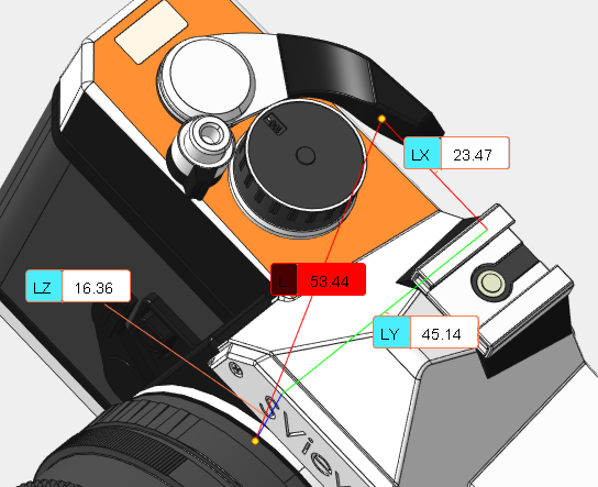
1.2 Operation
Click the Show XYZ button to enable or disable the XYZ projection display.
2. Smart Measure
2.1 Function
Automatically identifies the geometric relationship between two selected objects and generates corresponding distance or angle measurements intelligently.
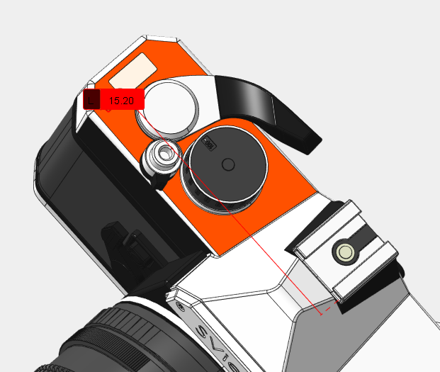
2.2 Operation
- Click the Smart Measure button to activate the command.
- Hover the cursor over the first target object and left-click to confirm the selection.
- Hover the cursor over the second target object; the preview measurement result will be displayed in real time.
- Left-click to confirm the second object and generate the official measurement result.
- Drag the measurement text to adjust its display position.
- Press Esc or click the button again to exit the command.
3. Chain Mode
3.1 Function
Creates continuous connected measurement groups. Each new measurement starts from the end point of the previous one to form a chained measurement sequence.
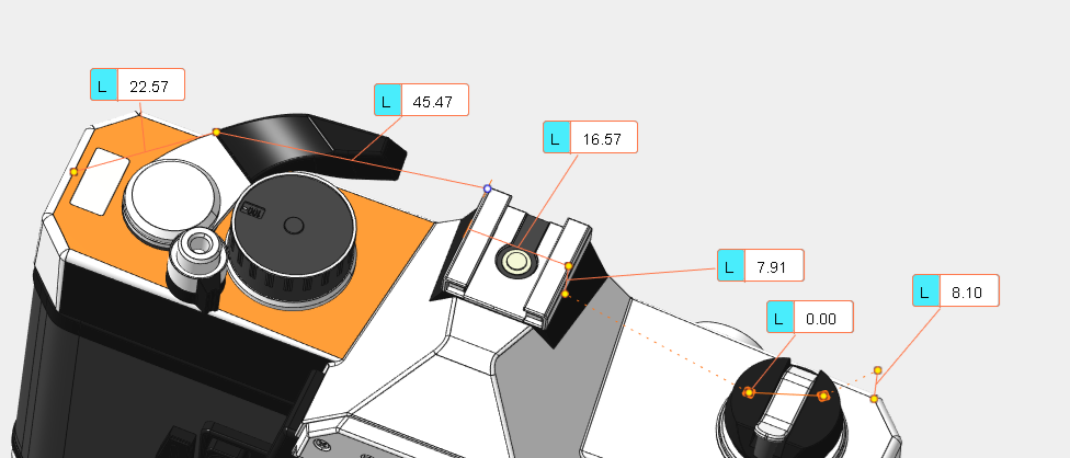
3.2 Operation
- Click the Chain Mode button to start chained measurement mode.
- Select the first measurement object.
- Select the second measurement object to generate the first segment measurement.
- Continue selecting additional objects; each new measurement will automatically connect to the previous endpoint.
- Right-click in the viewport to complete and exit the chain measurement.
4. Fan Mode
4.1 Function
Generates multiple measurement results with a unified common start point, suitable for fan-shaped multi-point detection scenarios.
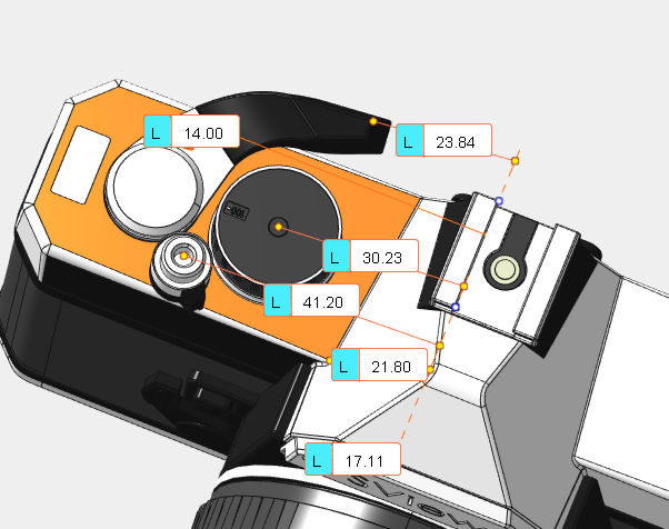
4.2 Operation
- Click the Fan Mode button to activate the function.
- Select the public start object as the unified measurement origin.
- Select the first end object to generate the initial measurement.
- Continue selecting multiple end objects; all measurements share the same start point.
- Right-click in the viewport to finish the sector scanning measurement.
5. Point to Point
5.1 Function
Measures the straight-line distance between two arbitrary picked points on the model.
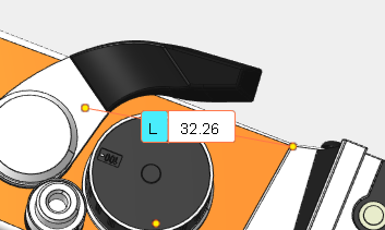
5.2 Operation
- Click the Point to Point button.
- Hover the cursor over the target position; the preview point will be highlighted, then left-click to confirm the first point.
- Move the cursor to the second target point; the preview measurement line and value will be displayed in real time.
- Left-click to confirm the second point and generate the measurement result.
- Drag the measurement text to adjust the display position.
6. Point to Line
6.1 Function
Calculates and measures the shortest vertical distance from a specified point to a target line or edge.
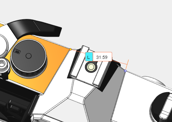
6.2 Operation
- Click the Point to Line button.
- Pick and confirm the target point.
- Hover the cursor over the target line or edge to preview the distance value.
- Left-click to confirm the line to generate the measurement result.
- Drag the measurement text to reposition it.
7. Point to Plane
7.1 Function
Measures the shortest vertical distance from a specified point to a target plane or planar face.
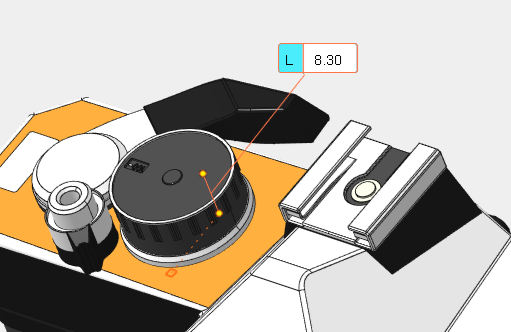
7.2 Operation
- Click the Point to Plane button.
- Pick and confirm the target point.
- Hover the cursor over the target face to preview the distance value.
- Left-click to confirm the face and generate the measurement result.
- Drag the measurement text to reposition it.
8. Line to Line
8.1 Function
Measures the shortest distance between two straight lines or model edges.
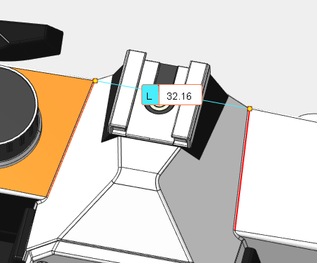
8.2 Operation
- Click the Line to Line button.
- Hover over the first line or edge, confirm by left-clicking after highlighting.
- Hover over the second line or edge; the preview measurement line and value will be displayed.
- Left-click to confirm the second line and generate the official result.
- Drag the measurement text to adjust its position.
- Press Esc or click the button again to exit.
9. Line to Plane
9.1 Function
Measures the shortest vertical distance between a straight line/edge and a planar face.
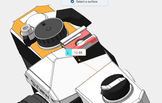
9.2 Operation
- Click the Line to Plane button.
- Pick and confirm the target line or edge.
- Hover over the target face to preview the distance value.
- Left-click to confirm the face and complete the measurement.
- Drag the measurement text to reposition it.
10. Plane to Plane
10.1 Function
Measures the shortest parallel distance between two planar faces.
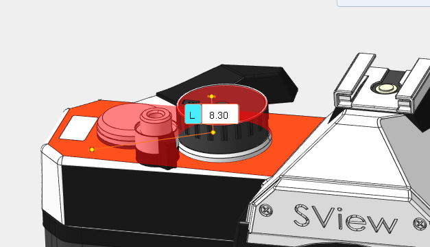
10.2 Operation
- Click the Plane to Plane button.
- Pick and confirm the first target face.
- Hover over the second face to preview the distance value.
- Left-click to confirm the second face and generate the result.
- Drag the measurement text to reposition it.
11. Axe to Axe
11.1 Function
Measures the center-axis distance between two cylindrical structural features.
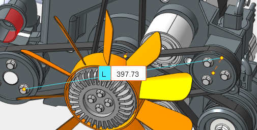
11.2 Operation
- Click the Axie to Axie button.
- Pick the first cylindrical face or edge to define the first axis.
- Pick the second cylindrical face or edge to define the second axis.
- The system automatically generates the axis-to-axis distance measurement.
- Drag the measurement text to adjust the display position.
12. Center to Center
12.1 Function
Measures the center-point distance between two circular or arc features.
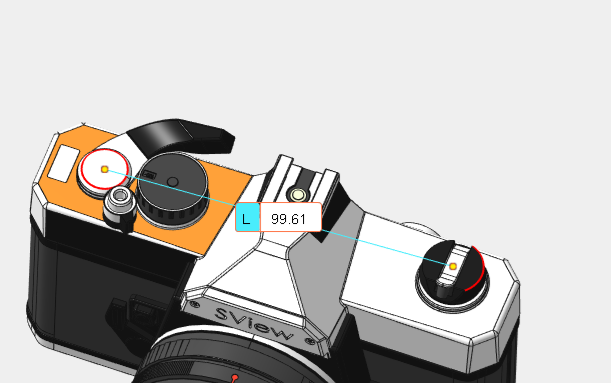
12.2 Operation
- Click the Center to Center button.
- Pick the first circle or arc feature.
- Pick the second circle or arc feature.
- The center-to-center distance result is generated automatically.
- Drag the measurement text to reposition it.
13. Thickness
13.1 Function
Detects and measures the wall thickness of the model at the picked surface point.
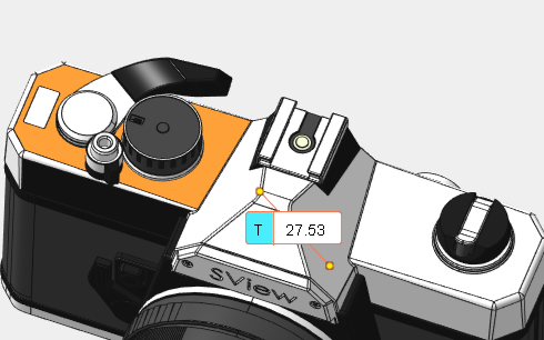
13.2 Operation
- Click the Thickness button.
- Hover over the model surface to preview the thickness value.
- Left-click to confirm the detection point and generate the thickness measurement.
- Drag the measurement text to adjust its position.
14. Angle Line to Line
14.1 Function
Measures the included angle between two straight lines or edges.
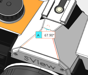
14.2 Operation

- Click the Angle Line to Line button.
- Pick and confirm the first line or edge.
- Hover over the second line or edge to preview the angle value.
- Left-click to confirm the second line and generate the angle result.
- Drag the measurement text to reposition it.
15. Angle Line to Plane
15.1 Function
Measures the included angle between a straight line/edge and a planar face.
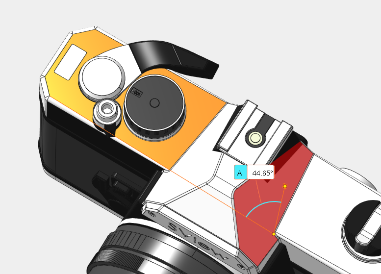
15.2 Operation

- Click the Line to Plane button.
- Pick and confirm the target line or edge.
- Pick and confirm the target face.
- The system automatically generates the line-plane angle measurement result.
- Drag the measurement text to reposition it.
16. Angle Plane to Plane
16.1 Function
Measures the dihedral angle between two planar faces.
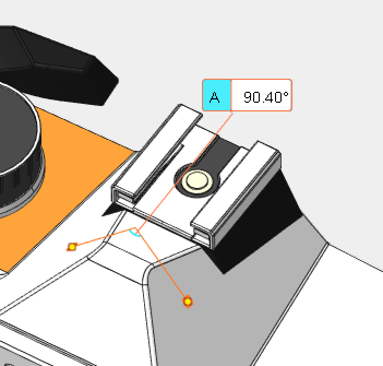
16.2 Operation

- Click theAngle Plane to Plane button.
- Pick and confirm the first face.
- Pick and confirm the second face.
- The plane-to-plane angle result is generated automatically.
- Drag the measurement text to reposition it.
17. Diameter
17.1 Function
Measures the diameter of a circle or arc feature.
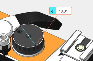
17.2 Operation
- Click the Diameter button.
- Hover over the circle or arc to preview the diameter value.
- Left-click to confirm the feature and generate the diameter measurement.
- Drag the measurement text to reposition it.
18. Radius
18.1 Function
Measures the radius of a circle or arc feature.
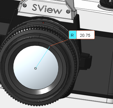
18.2 Operation
- Click the Radius button.
- Hover over the circle or arc to preview the radius value.
- Left-click to confirm the feature and generate the radius measurement.
- Drag the measurement text to reposition it.
19. Point Coordinates
19.1 Function
Queries and displays the world coordinate values of an arbitrary picked point on the model.
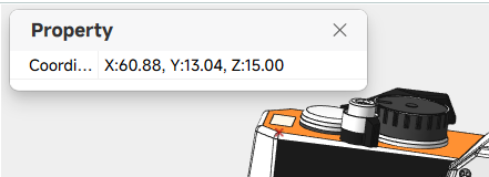
19.2 Operation
- Click the Point Coordinates button.
- Pick any point on the model surface; the coordinate data will be displayed in the property panel in real time.
20. Line Length
20.1 Function
Queries and displays the total length of a picked line or model edge.
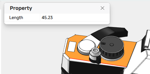
20.2 Operation
- Click the Line Length button.
- Pick the target line or edge; the length value will be displayed in the property panel.
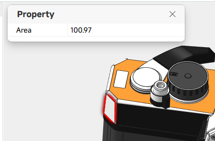
21. Face Area
21.1 Function
Queries and calculates the surface area of a picked model face.
21.2 Operation
- Click the Face Area button.
- Pick the target face; the area result will be displayed in the property panel.
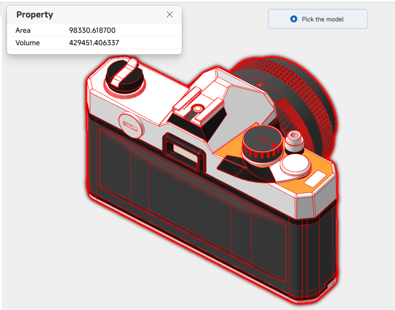
22. Model Volume
22.1 Function
Queries and calculates the overall volume of a picked model or solid body.
22.2 Operation
- Click the Model Volume button.
- Pick the target model or solid body; the volume data will be displayed in the property panel.
23. Recognize Edges and Faces
23.1 Function
Splits complex integrated model faces into independent selectable edges and faces, solving the problem of unselectable geometric features during measurement.
23.2 Operation
- Select the model parts that contain complex undecomposed faces.
- Click the Recognize Edges and Faces button.
- Confirm the pop-up prompt; the system will decompose complex faces and generate new selectable geometric elements.
- Use the decomposed features for subsequent measurement operations.
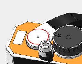
24. Find Center of Arc
24.1 Function
24.2 Operation
- Click the Find Center of Arcbutton.
- Hover over the target circle or arc to preview the center point.
- Left-click to confirm the feature and create the center point.
- Drag the text label to adjust the display position if required.
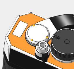
25. Find Center by 3Points
25.1 Function
25.2 Operation
- Click the Find Center by 3Points button.
- Pick the first point on the circumference.
- Pick the second point on the circumference.
- Hover to pick the third point and preview the calculated center point.
- Left-click to confirm the third point and complete center point creation.
26. Delete All
26.1 Function
Clears all measurement marks, data and objects existing in the current scene with one click.






全部评论