File Menu Guide
The File menu provides access to core file operations including opening, saving, exporting, system configuration, license management, and application control.
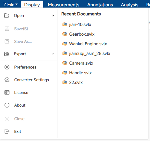
1. Open
Opens the file submenu. Two options are available:
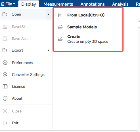
1.1 Open File
Opens a local 3D model file from disk.
- Click File > Open > Open File.
- In the file browser dialog, select one or more model files.
- The model loads into the viewport. If a model is already open, it will be closed first.
- Supported formats include SVLX (native), as well as CAD formats such as DWG, DXF, SLDPRT, SLDASM, CATPART, CATPRODUCT, and others. CAD files are automatically converted on import.
- Multiple files can be selected and opened simultaneously.
1.2 Open Sample
Opens a built-in sample model file included with the application.
- Click File > Open > Open Sample.
- Select a sample model from the dialog.
- The sample loads into the viewport.
1.3 Create
Creates a new empty 3D workspace.
- Click File > Open > Create.
- A new blank 3D document is created. If a model is already open, it is closed first.
- The default workspace panels (Model, View, Animation, etc.) are displayed.
- The new document is local and unsaved until explicitly saved.
1.4 Recent Documents
Displays a list of recently opened model files in the right panel of the **File > Open** menu. Each entry shows tthe file name and an
icon indicating whether it is a 2D or 3D model.
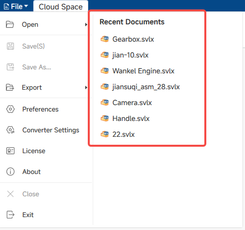
- Click File.The recent documents listcappears on the right side of the menu.
- Click a file name in the list to open it directlLy.
- Up to 10 recently opened files are retained.
- The list is updated automatically when a file is opened or saved.
2. Save
Saves the current file, overwriting the existing file on disk. Shortcut: Ctrl+S.
- Click File > Save or press Ctrl+S.
- If the file has not been saved before, a Save As dialog opens to choose a location.
- All modifications — including annotations, measurements, animations, section planes, materials, and model data — are saved.
- If multiple files are open simultaneously, save is not supported; a warning is shown.
3. Save As
Saves the current file to a new location or with a new filename.
- Click File > Save As.
- In the Save As dialog, choose a destination folder and enter a filename.
- Click Save to write the file.
4. Export
Opens the export submenu. Currently one export option is available:
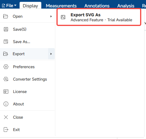
4.1 Export SVG
Exports the current viewport as an SVG vector image file.
- Click File > Export > Export SVG.
- The view automatically switches to orthographic projection.
- Configure the paper size and orientation in the export dialog (settings are shared with the SVG Export settings in Preferences).
- Click Export. A progress dialog appears while the file is being generated.
- The SVG file is saved to the selected path. The view returns to its previous projection when export completes.
- Cancellation is supported during the export process.
- Paper size and orientation are configured in Preferences > SVG Export.
5. Preferences
Opens the system preferences dialog. All settings take effect immediately unless otherwise noted.
5.1 Universal
Configures general interaction behavior, viewport background, and file cache settings.
| Setting | Description |
|---|---|
| Mouse Control Scheme | Mouse interaction preset. Options: SView, Pro/E, UG, CATIA, SolidWorks. |
|
Multiple Selection
|
Allow selecting multiple models simultaneously in the viewport.
|
|
Specify Rotation
|
When enabled, rotation is constrained to the selected object or point.
|
|
Center on Selection
|
Automatically centers the viewport on a selected model.
|
|
Continuous Rotation
|
Keep the model spinning after releasing the mouse button. |
| Only Load Assembly Tree | Load only the assembly tree structure without loading geometry. |
| Reverse Mouse Wheel | Invert the zoom direction of the mouse wheel. |
| 2D Missing Font Tip | Show a warning when a required font is missing in 2D drawings. |
| Scroll to Node | Automatically scroll the assembly tree to highlight the selected model. |
| Selected Effect | Visual style for highlighted/selected models. Options: Outline, Color, Highlight, Emphasis, X-Ray. |
| Select Display Color | Color used for the selected model highlight effect. |
| Outline Width | Thickness of the selection outline. |
| Background Type | Viewport background style. Options: Background Color, Image, Skybox. |
| Background Top Color | Top color for the gradient background. |
| Background Bottom Color | Bottom color for the gradient background. |
| Background Color Template | Predefined gradient presets for quickly setting the top and bottom background colors. |
| Use Cache | Enable or disable file caching for faster re-opening of previously loaded models. |
| Cache Directory | Folder where cached model files are stored. |
| Cache Folder Retention Time | Number of days cached files are retained before automatic cleanup. |
| Clean Cache | Manually deletes all cached files. Cached data cannot be recovered after deletion. |
5.2 Show
Configures viewport display options, preview color, upward direction, and lighting settings.
| Setting | Description |
|---|---|
| IgnoreErrorNormal | Ignore problematic normal vectors during rendering. |
| IsShowPMIs | Display Product and Manufacturing Information annotations. |
| ShowBrowseFrame | Show the current frames-per-second counter in the viewport. |
| IsShowBoundingBox | Display the bounding box for selected or all models. |
| IsShowEdge | Display model edge lines. |
| IsShowChildView | Display sub-component views. |
| ShowHotspot | Show icons for hotspot annotations. |
| IsShowCoordinate | Display the XYZ coordinate axis indicator. |
| IsUseAxisID | Display axis name labels (X/Y/Z) on the axis indicator. |
| UseModelBackground | Apply the background settings embedded in the model file. |
| IsUseDefaultView | Load the default saved view when opening a file. |
| IsUseSSAO | Enable screen-space ambient occlusion for more realistic depth shading. |
| IsUseShadowMap | Display ground shadow beneath models. |
| ShowRotateCenter | Show the rotation pivot point during navigation. |
| Preview | Enable pre-display rendering effects. |
| Preview Color | Color used for the preview/highlight effect. |
| Upward | Define the vertical axis for the scene. Options: +X, −X, +Y, −Y, +Z, −Z. |
| IsUseDefaultLight | Use the lighting configuration embedded in the model file. |
| Default Light Type | Select the default lighting preset. |
5.3 Performance
Configures model rendering performance, level-of-detail behavior, and graphics settings.
| Setting | Description |
|---|---|
| LittleModelCullerStyle | Method for culling small objects. Options: Model, Screen. |
| LittleModelCullerSize | Threshold ratio below which small models are culled. |
| IsUseLOD | Enable or disable level-of-detail reduction for distant models. |
| LODMatchType | How LOD levels are selected. Options: AutoCalculate, etc. |
| LODLevel | The specific LOD level used in Fixed or No Higher Than modes. |
| ScreenRatio | Screen-space ratio thresholds for each LOD level (LOD0–LOD5). |
| IsCheckSamilarMaterial | Detect and share duplicate material data to reduce memory usage. |
| OpenGL Version | OpenGL version used for rendering. Options: OpenGL2, etc. |
| MultiSamplingAntiAliasing | Smoothing level for edges. Options: Off, X2, X4, X8. |
| IsProgressiveRendering | Gradually render the scene rather than all at once when loading large models. |
5.4 Function
Configures annotation visibility, section plane display, annotation and hotspot text styles, and measurement units and colors.
| Module | Setting | Description |
|---|---|---|
|
Function Demo |
IsAnnotationVisibleWithModel | Show or hide annotations together with their associated model components. |
| IsAnnotationSelectedWithModel | Highlight annotation when its associated model is selected. | |
| IsModelSelectedWithAnnotation | Highlight model when its associated annotation is selected. | |
|
Clip |
ClipPlaneContourLine | Display the intersection contour lines on the section cut. |
| Show Section Plane | Toggle visibility of the section plane indicator. | |
| Show Section Capping | Toggle visibility of the solid fill cap on cut models. | |
| ClipPlaneColor | Color of the section cut plane surface. | |
| ClipLineColor | Color of the section contour lines on cut geometry. | |
| CoverColor | Fill color for the capping (solid cap) surface. | |
| CoverColorMode | How the capping color is applied. Options: UseCoverColor, etc. | |
|
Annotation |
AnnotationFontColor | Color of annotation text. |
| AnnotationFont | Font face for annotation text. | |
| Annotation FontSize | Font size for annotation text. | |
| AnnotationFrameColor | Border color of annotation callout boxes. | |
| AnnotationFillColor | Background fill color of annotation callout boxes. | |
| AnnotationLeaderColor | Color of annotation leader lines. | |
| SeQuenceAnnotationMaxCount | Maximum number allowed for sequential/numbered annotations. | |
|
Hotspot |
HotSpotTextColor | Color of hotspot label text. |
| HotSpotFrameColor | Border color of hotspot label boxes. | |
| HotSpotFillColor | Background fill color of hotspot label boxes. | |
| HotSpotFont | Font face for hotspot labels. | |
| HotSpotFontSize | Font size for hotspot labels. | |
|
Measurement |
MeasureFont | Font face for measurement labels. |
| MeasureFontSize | Font size for measurement labels. | |
| MeasureValueFontColor | Color of the numeric result in measurement labels. | |
| MeasureTitleFontColor | Color of the measurement title text. | |
| Decimal Places | Number of decimal digits shown in measurement results. | |
| length units | Unit for linear distance measurements. | |
| area unit | Unit for area measurements. | |
| volume unit | Unit for volume measurements. | |
| weight units | Unit for mass/weight measurements. | |
| ShowMaxDistance | Display the maximum distance result in distance measurements. | |
| ShowMinDistance | Display the minimum distance result in distance measurements. | |
| MeasureTitleType | Format for measurement label headings. Options: Symbol, English, Chinese. | |
| MeasureTitleBackground | Background color for the measurement title area. | |
| MinDistanceColor | Color used for the minimum distance indicator. | |
| MaxDistanceColor | Color used for the maximum distance indicator. | |
| MeasureFrameColor | Color of the measurement label border. | |
| MeasureLeaderColor | Color of measurement leader lines. | |
| MeasureDir | Orientation of distance measurements. Options: Perpendicular To Surface, etc. |
5.5 Log
Configures log output path, logging level, automatic cleanup, and manual log cleanup.
| Setting | Description |
|---|---|
| LogPath | Folder where log files are saved. |
| OpenLog | Enable or disable log recording. |
| ExportLevel | Minimum severity level to log. Options: Error, Warning, Info, Debug. |
| AutoClearDays | How many days to keep log files before automatic deletion. |
| CleanLog | Manually deletes all saved log files. |
5.6 Page Size
Configures the page dimensions and orientation for exported illustrations.
| Setting | Description |
|---|---|
| Pape Option | Page size preset. Options: Viewport, etc. |
| Width | Page width in millimeters. |
| Height | Page height in millimeters. |
| Landscape / Portrait | Page orientation. |
6. Converter Settings
Opens the converter configuration dialog. The converter is used when opening CAD files that require format conversion before loading.
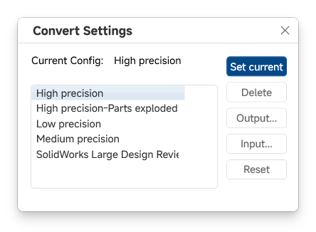
- Click File > Converter Settings.
- A list of available conversion configuration profiles is shown.
- Select the desired profile and click Set Current to activate it. The configuration file is copied to the active converter path.
- To import a custom configuration, click Import. Select a
.configfile from disk and confirm. The file is copied into the configuration list. - To remove a configuration, select it and click Delete.
- To export a configuration, select it and click Output, then choose a destination path.
- Click OK to close the dialog.
- Preset profiles include configurations such as high-precision with or without part decomposition.
- Imported custom profiles are added to the list and can be selected, exported, or deleted.
- A configuration that is currently in use cannot be deleted or re-imported.
- The selected configuration applies to all subsequent CAD file imports.
7. License
Opens the license management window. Displays the current license status and provides options to apply for or import a new license.
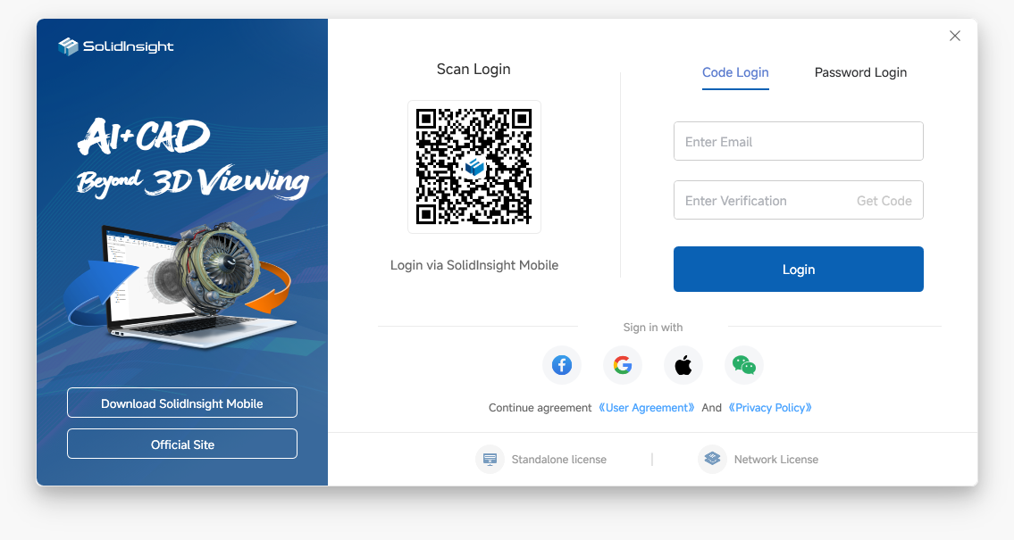
- Click File > License.
- If a valid license is found, the license information window opens showing details such as license type, expiry date, and authorized modules.
- If no valid license is found, a dialog prompts you to: Apply: Opens the license application website in a browser.Import: Opens a file browser to select and import a
.liclicense file.
8. About
Displays the application version and build information.
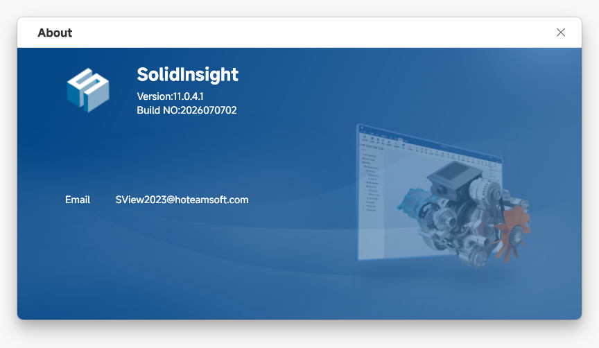
- Click File > About.
- The About window shows the application name, version number, build ID, and underlying engine versions.
- Click Close to dismiss the window.
9. Close
Closes the currently open file and clears the viewport.
- Click File > Close.
- If there are unsaved changes, a prompt appears: Yes: Save the file, then close; No: Close without saving; Cancel: Cancel the close operation.
10. Exit
Exits the application.
- Click File > Exit.
- If there are unsaved changes in the open file, the same save prompt as Close is shown.
- After confirming, the application window closes.






全部评论