Annotations Tab Guide
The Annotations tab provides tools for adding 2D and 3D markup to models, including magnetic lines, arrows, freehand sketches, labels, callouts, auto numbering, multi-lead labels, stamps, detail captures, associative paths, hotspots, and actions. Users can also delete existing annotations and manage leader lines through merge and share operations.

1. Magnetic Line
1.1 Function
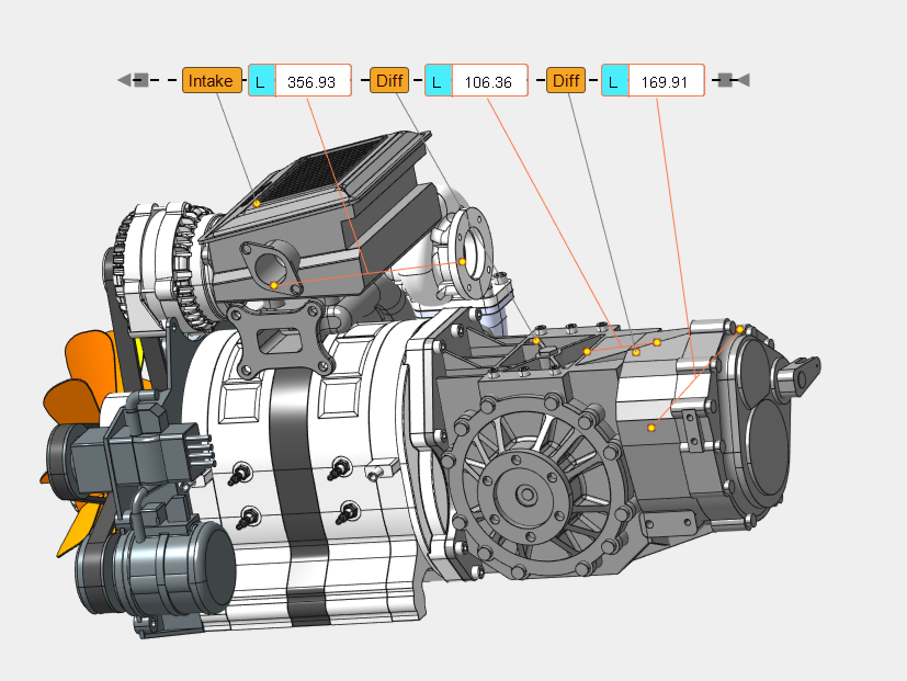
Creates a straight alignment line that helps quickly align annotations. After the command is exited, the magnetic line can be adjusted by dragging either endpoint to stretch or rotate it. While an endpoint is being dragged, the line automatically snaps to existing annotations, including text labels, callout numbers, measurement annotations, and multi-leader text/number annotations.
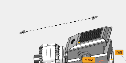
1.2 Operation
- Click the Magnetic Line button.
- Move the cursor to any position in the 3D viewport to define the anchor point. A preview line is displayed.
- Press the left mouse button to confirm the first point.
- Move the cursor to set the second point (line end). The line length updates in real time.
- Press the left mouse button to confirm the second point. The magnetic line is created.
- Press Esc or click the button again to exit the command.
- Move the cursor over either endpoint of the magnetic line and drag it to stretch or rotate the line. The opposite endpoint stays anchored, and the line stretches or rotates along its axis. While dragging the endpoint, the line automatically snaps to nearby annotations (text labels, callout numbers, measurement annotations, and multi-leader text/number annotations).
2. Arrow
2.1 Function
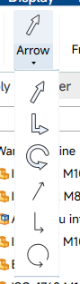
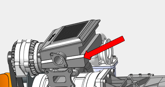
Creates a straight or circular arrow annotation. After the command starts, the ribbon switches to the Format Editing tab to set the arrow style, fill color, transparency, and direction.
2.2 Operation
- Click the Arrow split button and select the arrow type to start the command.
- In the Format Editing tab, configure the arrow style, fill color, transparency, and direction.
- For a straight arrow, move the cursor to preview the start point and arrow, click to set the tip, move to extend the tail, and click again to finish.
- For a circular arrow, click to set the center (snap to a cylindrical or conical face to align to its axis), move to set the radius and click, then move to set the arc angle range and click to finish.
- Press Esc or click the button again to exit the command.
3. Freehand
3.1 Function
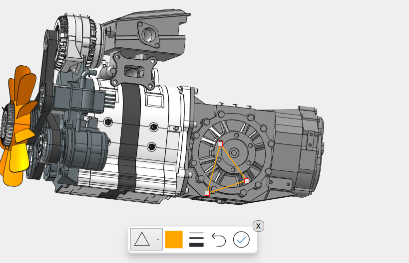
Draws freehand strokes or predefined shapes (line, circle, rectangle, triangle) on the viewport.
3.2 Operation
- Click the Freehand button. A drawing toolbar appears at the bottom of the viewport.
- In the toolbar, select a stroke type from the drop-down:Line, Circle, Rectangle, or Triangle.
- Select a color and line thickness using the color and width buttons.
- Press and hold the left mouse button on the viewport and drag the cursor to draw.
- Release the left mouse button to finish the current stroke.
- Click Undo to remove the last stroke, or click Confirm to finalize the drawing.
- Click the Close button on the toolbar to exit freehand mode.
4. Label
4.1 Function
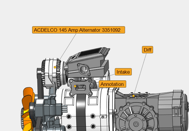
Creates a text annotation with an optional leader line and frame.
4.2 Operation
- Click the Label button.
- The ribbon automatically switches to the Format Editing tab. In this tab, configure the label style, including font, font size, font color, border style (borderless or rounded), background color, frame color, and leader line color. Enable the Fixed Screen option if the label should maintain a fixed screen size.
- Move the cursor to the model and press the left mouse button to set the leader anchor point (first point).
- Move the cursor to the desired text position. A preview label is displayed while the cursor moves.
- Press the left mouse button to set the text position (second point). A text input window appears.
- Enter the label text and close the input window. The label is created.
- If the first and second points coincide, the text input window appears immediately after the single click.
- Press Esc or click the button again to exit the command.
5. Callout
5.1 Function
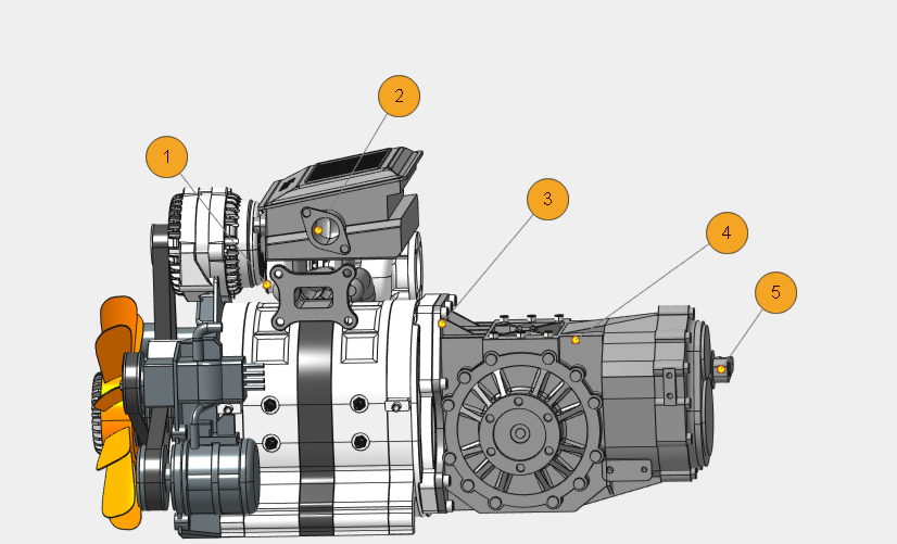
Creates a numbered callout annotation. The number is automatically incremented based on existing callouts.
5.2 Operation
- Click the Callout button.
- Move the cursor to the model and press the left mouse button to set the leader anchor point.
- Move the cursor to the desired callout position. A preview callout is displayed.
- Press the left mouse button to set the callout position. A number input window appears with the next sequential number.
- Accept or edit the number and close the input window. The callout is created.
- Press Esc or click the button again to exit the command.
6. Auto Numbering
6.1 Function
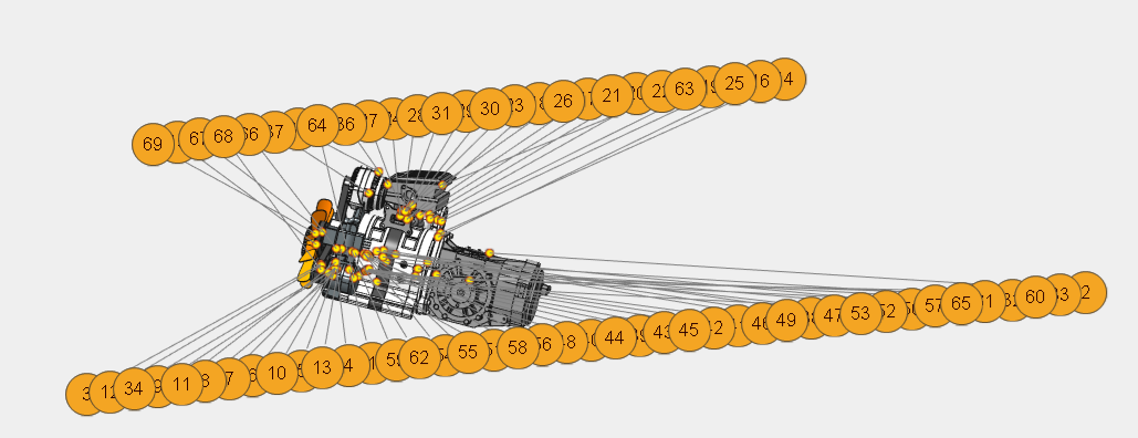
Automatically generates numbered callouts for the parts in the current scene according to a layout direction.
6.2 Operation
- Select the models to be labeled. If no model is selected, the top-level assembly is used.
- Click the Auto Numbering button.
- The system analyzes the scene and creates numbered callouts for each part using the configured layout (surround, horizontal, or vertical).
- The callouts use the current annotation style settings (leader, frame, font, color).
7. Multi-lead Label
7.1 Function
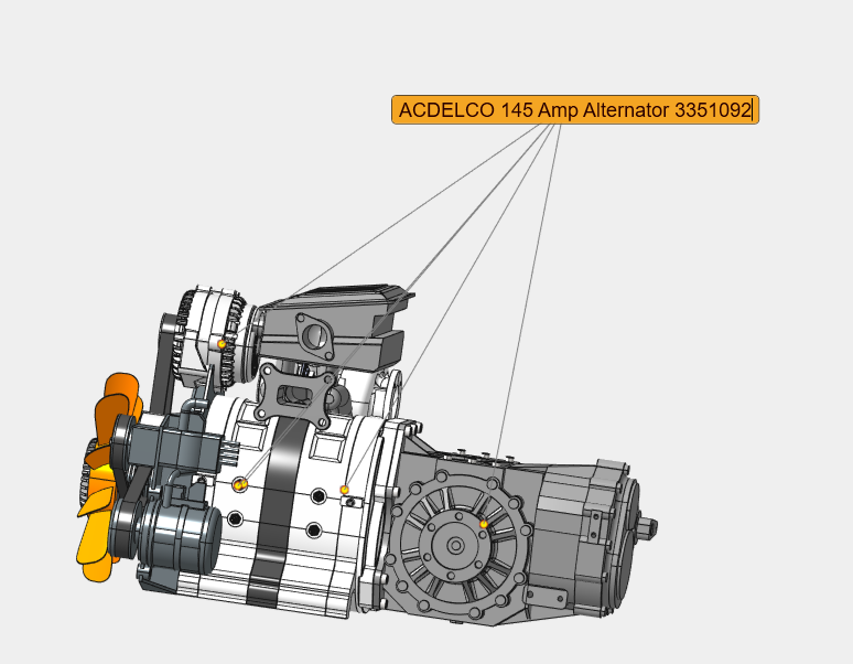
Creates a single text label with multiple leader lines pointing to different model parts.
7.2 Operation
- Select the model parts to be annotated.
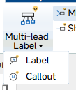
- Click the Multi-lead Label button. Choose Multi-lead Text Label or Multi-lead Number Label from the drop-down.
- Move the cursor to the first anchor point on a selected part. A preview annotation is displayed.
- Press the left mouse button to set the text position. A text input window appears.
- Enter the text and close the input window. The multi-lead label is created.
- Additional leader lines can be added by editing the annotation after creation.
8. Merge Leads
8.1 Function
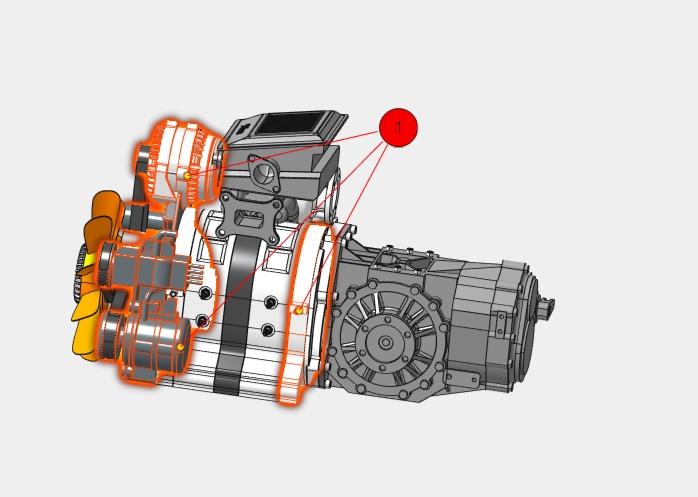
Sets the default multi-lead annotation style so that all leader lines are merged into a single shared leader.
8.2 Operation
Click the Merge Leads toggle button. Subsequent multi-lead annotations are created with merged leaders.
9. Share Lead
9.1 Function
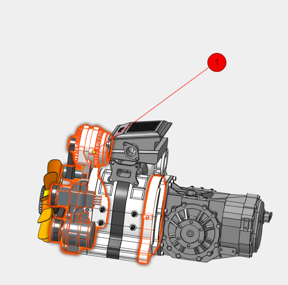
Sets the default multi-lead annotation style so that each leader line remains independent.
9.2 Operation
Click the Share Lead toggle button. Subsequent multi-lead annotations are created with separate leaders.
10. Delete Annotation
10.1 Function
Removes all annotations from the scene.
10.2 Operation
Click the Delete button. All annotation objects are cleared immediately.
11. Stamp
11.1 Function
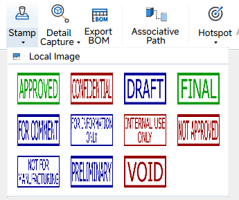
Inserts a predefined seal image into the viewport.
11.2 Operation
- Click the Stamp button. The seal selection drop-down opens.
- Select the desired seal from the list.
- Move the cursor to the desired insertion position.
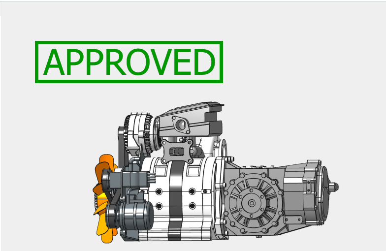
- Press the left mouse button. The seal image is inserted at the selected position.
- The inserted seal can be dragged to adjust its position.
12. Local Image
12.1 Function
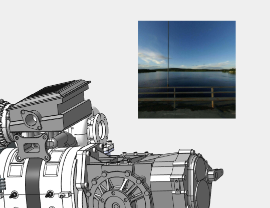
Inserts an image from the local file system into the viewport.
12.2 Operation
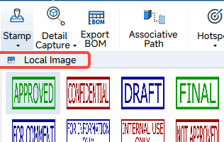
- Click the drop-down arrow on the Stamp button and select Local Image.
- In the file dialog, select the image file and confirm.
- The image is inserted into the viewport, scaled to fit the view if necessary.
- The inserted image can be dragged to adjust its position.
13. Detail Capture
13.1 Function
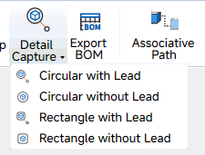
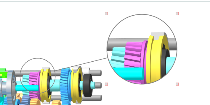
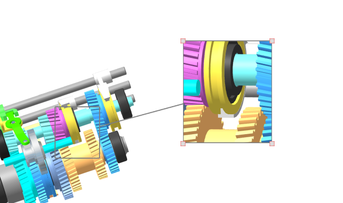
Creates a magnified detail view of a selected viewport area. Four capture modes are available: Circular with Lead, Circular without Lead, Rectangle with Lead, and Rectangle without Lead.
13.2 Operation
- Click the Detail View split button and select the desired capture mode from the drop-down gallery.
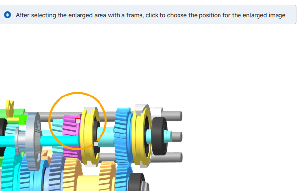
- For circular modes, press and hold the left mouse button to set the center of the detail area, drag the cursor to set the radius, and release the left mouse button to create the detail view.
- For rectangular modes, press and hold the left mouse button to set one corner of the rectangle, drag the cursor to define the opposite corner, and release the left mouse button to create the detail view.
- In no-line modes, the detail view is created without a visible boundary line.
- After creation, drag the detail view or its boundary to adjust position and size.
13.3 Context Menu
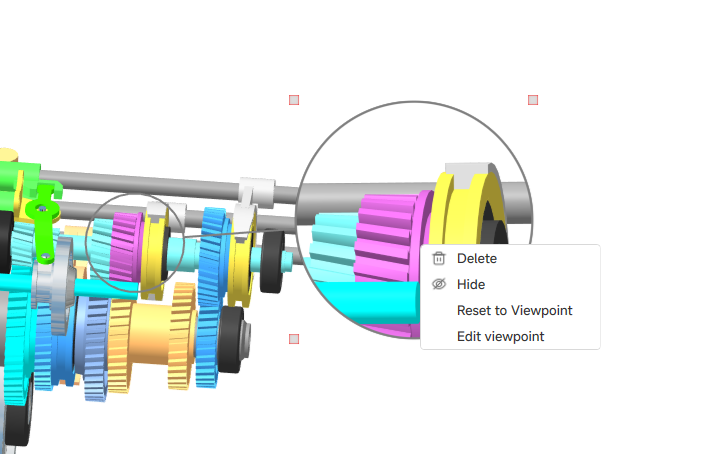
- Right-click the detail capture to open the context menu. The menu provides the following options:
- Delete: removes the selected detail capture.
- Hide: hides the selected detail capture.
- Reset to View Point: resets the detail view to the original capture viewpoint.
- Edit Digger View: enters edit mode. A bounding-box dragger appears; drag the handles to resize the capture area, or drag the center to move it.
14. Export BOM
14.1 Function
Exports the bill of materials (BOM) of the current assembly using a configurable template.

14.2 Operation
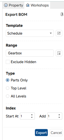
- Click the Export BOM button. The BOM export dialog opens.
- In the Template section, select an existing template or click the edit icon to configure the export fields.
- In the Range section, set the export scope and check Exclude Hidden if hidden parts should be omitted.
- In the Type section, select the export level:Parts Only, Top Level, or All Levels.
- In the Index section, set the Start At value and the Add increment.
- Click Export, choose the destination path and file format in the file dialog, and confirm. The BOM file is generated.
15. Associative Path
15.1 Function
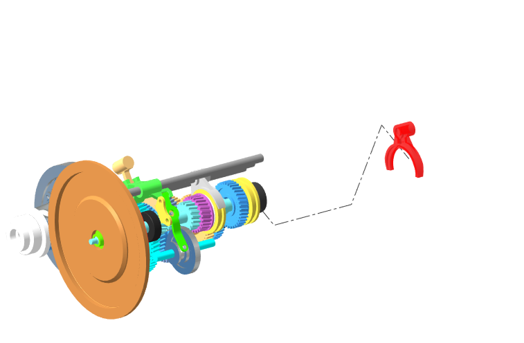
Uses lines to decompose parts according to their assembly relationships. When a model changes position, associative path leader lines are generated to show the change.
15.2 Operation
- Click the Associative Path button. The Associative Path dialog opens.
- In the dialog, click Add and select the parts to be included. The selected parts appear in the list with their serial number and instance name.
- In the Path drop-down, select the coordinate system (for example,Global Coordinate).
- In theAxis Sort drop-down, select the axis order (for example, XYZ).
- Click OK. The associative path lines are generated for the listed parts.
- When the model position changes, the path leader lines are updated to reflect the new positions.
- To edit a path, select it in the viewport. Key points are displayed and can be dragged with the manipulator.
16. Hotspot
16.1 Function
Creates an interactive hotspot that triggers one or more actions when clicked.
16.2 Operation
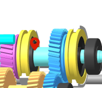
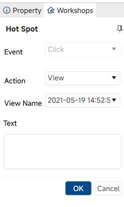
- Click the Hotspot button. The hotspot creation dialog opens.
- In the dialog, configure the action to be triggered (for example, switching to a view or playing an animation).
- Enter a description and set the text style (font, frame color, fill color, text color).
- Move the cursor to the viewport and press the left mouse button to place the hotspot icon.
- Click the confirmation button in the dialog. The hotspot is created.
- Existing hotspots can be edited by selecting them and reopening the command.






全部评论